The Scam Bike
Last year I was introduced to man who is a native of Mobile and now lives in Boston. On a visit to Mobile a mutual friend brought him to my shop to look at my collection. Although he is a life-long rider and has a late model BMW GS he was new to the vintage bike scene. When he entered my shop he immediately exclaimed “oh I had one of those and I had one of those”. As a teenager he had an Earls fork BMW R60/2 and a Pre-unit Triumph 650 here in Mobile. Soon I put him on my Triumph Bonneville and we went riding. That was all it took and he was hooked. After he went back to Boston we began trading emails and he was debating what sort of bike he should buy to get started in the hobby. I suggested either a BMW or a Triumph. Parts supply is excellent for both brands and their popularity and value just keeps building. Also, since he spent his youth with both brands either would have special meaning to him. After weeks of searching the internet he found a 1960 white BMW R60 in Mississippi for $3000 that looked very clean. When my friend contacted the seller my friend explained that he had a friend in Alabama that could inspect the bike and pick it up if a sale was made. The reply came back that the bike was now in Portland Oregon but he would be happy to have it shipped to Boston. To further complicate the deal the seller claimed to be working on a cruise ship out of England and the money would have to be sent there. My friend agreed and arranged to have a money order in exchange for a shipping invoice. Just to be sure he called the shipper immediately. Sure enough the invoice was a phony. The shippers never heard of the seller indicating it was a scam so he canceled the cash transfer immediately. But that is not the end of the story. A computer-savvy colleague checked the pictures of the bike that were emailed to him against Google image. The pictures came from an eBay bike that had been up for bid several months previously and, get this, the bike was in Boston! The bike had not sold so my friend made arrangements to see it. The seller had been asking $12,000 but a sale was struck for much less. My friend asked if he could ship it to me to clean up and check it out over the winter and he would pick it up in the spring.
A week later an 18 wheeler pulled up in front of my house with the logo “keyboard freight” on the side. I thought that was an awfully big truck for shipping computer keyboards. He opened it up and it was full of pianos and motorcycles. What started as a piano (hence the name keyboard) shipping business had expanded to include motorcycles. Each motorcycle was strapped to a pallet which had retractable casters underneath. The driver snapped up the casters and we rolled the pallet to the lift gate. On the ground we unstrapped the bike and rolled it off. The empty pallet was then neatly stashed in a receptacle on the wall of the truck.
BMW made a series of twin cylinder motorcycles from 1955 to 1969. They consisted of the R50 (500 cc and 26 HP) the R60 (600cc and 30HP) and the R69. They all shared the same chassis, engine block and running gear. The R69 had a highly tuned 600cc engine with hotter cams and higher compression pistons and made 42HP. They all used the Earls leading link front fork except the US models that appeared late in the run which had telescopic forks. The Earls fork was used because it was better suited to sidecar use where the forks have to endure high lateral forces during turns. Many of these bikes were used as sidecar tugs, especially in Europe. The Earls forks have alternative holes for the swing arm pivot which decreases the trail for more neutral steering when the sidecar is attached. In 1960 a few changes were made to the models and the R50 and R60 acquired the /2 suffix. The R69 became the R69S. There is no inclusive name that covers all of these models except the cumbersome “1955-1969 BMW twins”. My friend's bike is an R60 while I have a 1965 R50/2.
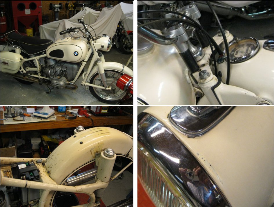
The bike was your typical 10 footer - looked good from 10 or more feet away. The paint on the tank and fenders was pretty good except for an ugly dent in the front fender and a nasty solder job at the front of the tank near the steering head. The rear of the bike was filthy with oil which turned out to be from a leaky rear bevel drive. The spokes were badly rusted as were the cylinders. Somewhere along the line it acquired a set of ape hanger handle bars. The tires were weather checked. On the plus side it started right up and the motor sounded decent. A trip around the block revealed a smooth transmission but no rear brake. The electricals seemed ok and the generator was charging. The frame was the worst part. It had been touched up with poorly matching pant and was badly scratched up. The area around the battery and rear fender was corroded from spilled acid.
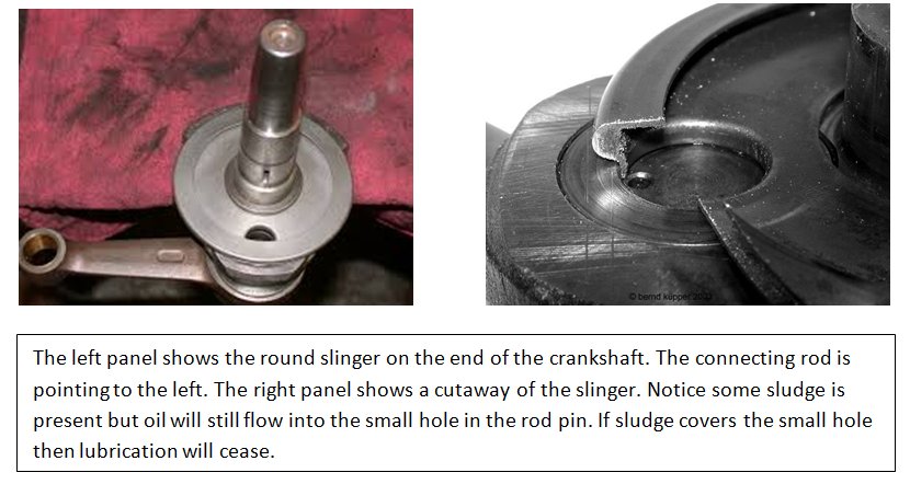
The bike showed 60,000 miles which is getting up there even for a BMW. Nothing was known about the motor’s service history. The Achilles heel of the 1955-1969 BMW twins is the oil slingers. These little disks sit on either end of the crank shaft (see picture below). The rim is wrapped around to form a trough several mm wide and about a cm deep. A hole in the pan leads to a oil journal in the crank pin. The rod attaches to the crank pin with precision roller bearings. The oil pump squirts oil into the grove of the slinger and centrifugal force pushes the oil into the hollow crank pin and through a small hole into the rod bearings.
Roller bearings do not need a high pressure feed like a plain bearing so this constant dribble of oil works fine. The problem is that centrifugal force also packs particulate matter into the groove and crankpin until eventually they both become full of sludge (the right hand figure below shows some moderate sludge build up). When sludge covers the hole in the crank pin the oil flow stops, and the rod bearing, now starved for oil, begins to wear quickly. Soon a rod comes a knocking – or worse. These motors do not have an oil filter to remove the sludge in the oil like a modern bike so the only way to prevent this problem is to keep the oil clean by changing it often (every 600 miles is recommended in my Clymer book). Some of the sludge is iron shavings caused by normal wear and a magnetic oil drain plug will catch most of that. The majority, however, is carbon resulting from the combustion of the fuel.
So the question was “how are the slingers?”. With the cylinders off the outer edge of the slingers can clearly be seen but unfortunately you cannot see inside them. The only way to check them is to remove the crankshaft with a complete tear-down. Any BMW with 60,000 miles is overdue for a slinger cleaning. On the other hand they might have been cleaned just 10,000 miles ago. My friend said can you arrange to have them cleaned so we won’t have to worry. Suddenly the clean up looked like it was turning into a full-blown restoration. I agreed to do it. I sent the motor to Bench Mark Works (BMW get it?) in Sturgis Mississippi where BMW Guru “Vech” Vechorik would do the honors. Vech sent me a special crate for the motor. The cylinders, pistons, and transmission were removed from the engine and the resulting short block is then bolted to mounts in the crate and shipped back to Sturgis.

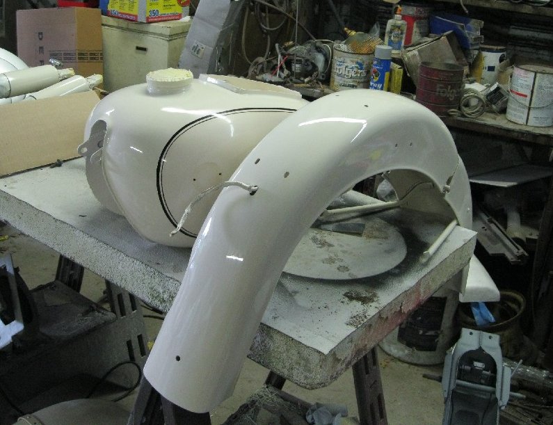
With the motor out a repaint seemed appropriate. The bike was completely disassembled. The frame forks and swing arms were sent to Phil Ostercamp in Grand Bay, AL for media blasting to remove all rust and paint. They came back finished in epoxy primer and looked great. The sheet metal went to P&E body shop in Theodore AL for paint. The bike had what appeared to be original factory paint and pinstripes on the tank and fender. P&E matched the color with a spectrograph at the PPG paint store. Single stage enamel with a polyurethane hardener was used. The dent was fixed in the front fender and all scratches were carefully touched up in the fender and tank with an artist’s brush and spot spraying carefully avoiding the pin stripes. Then they were given several coats of clear to protect the original paint below and give a uniform gloss. Unfortunately the rear fender was beyond saving. The rusty springs in the Denfield seat had been rubbing on the fender and scratched much of the paint off. Battery acid had done a job on it as well. P&E repainted it and had a local pin stripe artist, Don Tanner, match the stripes on the tank and front fender. The rear fender was also clear coated to protect the stripes. The frame, headlight, toolbox cover, etc simply got the single stage enamel with hardener. The air cleaner and hub caps were painted with a ford silver color. The cylinders and heads were bead blasted and the cylinders were painted black.
When I removed the pistons from the motor I carefully tested the rod bearings seeing if they turned smoothly and had no free play. They seemed OK. However, the report came back from Vech that the slingers and crank pins were full of sludge and after cleaning the crankshaft in the parts washer the rod bearings were found to be worn beyond their service limits. Furthermore, there was unacceptable wear on the camshaft and tappets due to inadequate lubrication. Motor oils in the 1960’s had a high zinc content which was required to lubricate the bearing surfaces used in these bikes. To reduce heavy metal pollution, modern oils no longer use the zinc additive and motor designers now use alloys that do not require such a robust lubricant. Old BMW’s tend to wear quickly if modern oils are used. Vech recommends Valvoline 40 weight VR1 racing oil to avoid such problems in your old BMW. This oil would also be a good choice for Triumphs and BSA’s of that era as they suffer from the same problem.
The crankshaft would require rebuilding with new roller rod bearings. The camshaft and tappets could either be replaced or reground by Cycle Works in Kansas City for less than 1/3 the replacement cost ($250). I chose the latter. Cycle Works, by the way, has a full line of special tools for working on Vintage BMWs. I bought a tool from them for removing the wheel bearing retainers. Using the repaired internals, the motor was reassembled complete with new main bearings and seals. Vech also installed a new coil, points and condenser and timed the motor. To avoid another freight charge I talked him into bringing the motor to Barber’s Vintage festival where I picked it up.
While the motor was getting its makeover in Mississippi I tackled the rear drive. The problem was a bad seal that had allowed gear oil to leak all over the brakes. Moto Guzzi used a similar bevel-drive system in their original V twin bikes but put it on the side opposite the brake drum so any leaks would not kill the brakes. Not so with the BMW. All bearings felt smooth and tight so I replaced the two oil seals in the drive and with a new gasket put it back together. There was a small puddle of oil under the transmission so I replaced the three oil seals in it as well. The front seal is easy but the rear seal (which is the one that was leaking) requires removing the output flange. The flange is on a taper and is held on with a castle nut that requires a special tool (obtainable from Cycle Works). The transmission seemed fine so I did not go into it. I ordered a brake relining kit from Vech for the rear wheel. It comes with a strip of brake lining, copper rivets and detailed instructions on how to mount them. They are half the cost of shoes with installed linings and all you need is an electric drill and a pop rivet tool.
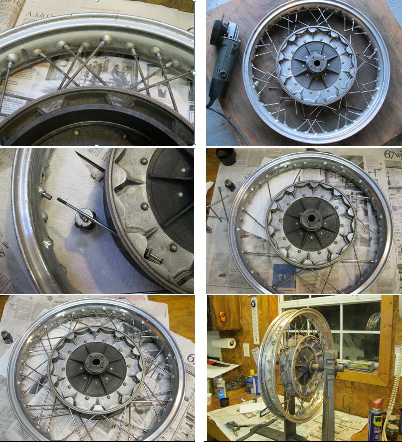
The wheels needed new spokes. Somebody had replaced the original cad-plated spokes with chrome plated ones but they were now badly rusted. I broke the wheels down by removing the tires and cutting out the spokes with an angle grinder (see top right picture below). I polished the rims and then relaced the wheels with stainless steel spokes from Vech. He had nice sets for about $80 per wheel. The wheels on these models are the easiest of any to lace. The spokes are of the “nail” type. The end opposite the nipple has a flat head on it like a carpenter’s nail. You first center the hub inside the rim on a flat surface. Then stick the spoke through a spoke hole in the hub until it touches the rim. Turn the rim until a hole in the rim lines up with the spoke. Then insert a nipple through the hole and screw it on to the spoke. Repeat that until all spokes are in place and the wheel is ready for truing. After truing the wheel I cleaned and packed the tapered roller bearings in the wheels. A unique feature of the /2 wheels is that they are both identical and interchangeable. These bikes were often used as sidecar tugs and you could carry a spare wheel on the back of the Steib sidecar that would fit all 3 wheels. I finished the wheels with a set of German Heidenau tires.
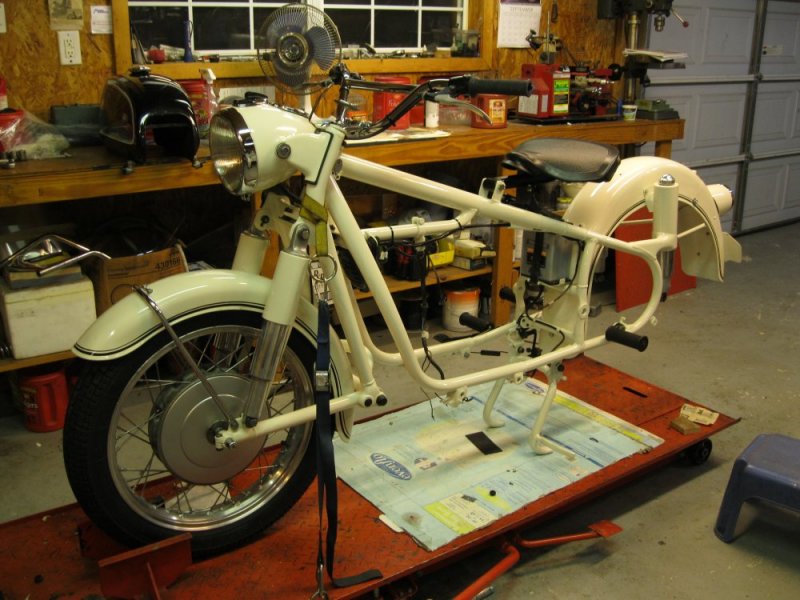
It was now time to put everything back together I started with the front forks, then the shock absorbers and front leading link. The center stand was installed along with the front wheel and now the bike was on its feet. Rusty nuts and bolts had to be replaced but many of the original 8 and 10 mm bolts that weren’t rusty could be saved by polishing them on a brass wire wheel and putting a coat of clear enamel on them. Most of the 6 mm bolts were rusty and not usable. I did buy a set of polished stainless front fork bolts. They were beautiful. The head light went on as did the fenders, handlebars and seat. My friend wanted the American pattern handlebars with the cross brace and a solo seat. I ordered both from Vech. The bars were from Germany and the label in German clearly had the word "motocross". I also needed to buy the stainless steel risers that mount the bars. I selected the Denfield solo seat which is rubber rather than spring mounted.
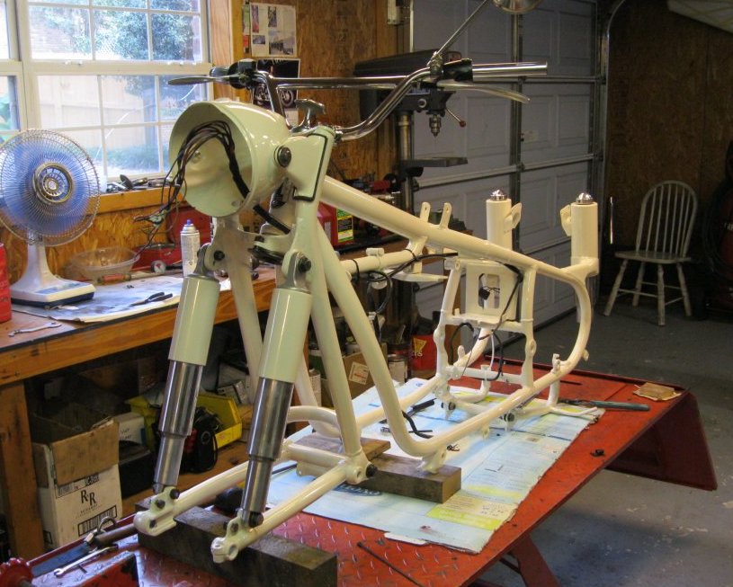
Now it was time to install the motor. BMW boxer twins are all mounted with two stout bolts that pass through the bottom frame members and matching holes in the engine block (see picture above). That’s it. A friend helped me position the 50 lb short block and we fed the bolts through the holes and the motor. It was that easy. The polyurethane paint over epoxy primer was very scratch resistant but I didn’t want to take any chances. I took pieces of corrugated cardboard and wrapped them around the frame tubes. A little masking tape held them in place. That keeps the motor from gouging the paint while it is jockeyed into place.
Next came the cylinders. It looked like the bike had recently been fitted with new pistons. They were one size over stock and the hone marks were still quite visible on the cylinder wall. Oddly enough, the rings were not within service limits with gaps that were too wide. It looked like whoever fit the rings filed too large a gap in them. Whatever the case, I ordered a new set of rings and filed them to specification. The pistons were mounted on the rods and cylinders were fitted using a ring compressor. The cylinders were then torqued down. I lapped the valves to ensure a good seal and installed the heads. I set the valves clearance and attached the carburetors after a disassembly, inspection and cleaning. The motor was finished.
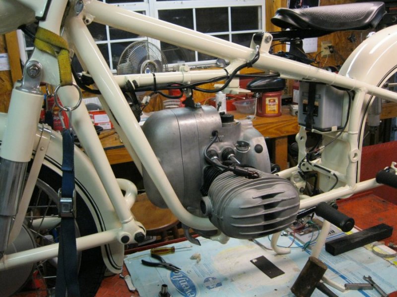
The transmission only bolts to the motor. The spines on the transmission shaft were coated with a thin film of grease where it passes through the clutch. I Slid the transmission onto the motor and bolted it in place. Next came the rear swing arm. The swing arm pivots in a set of tapered roller bearings which were nasty. I sourced a new set at a local bearing store. The question was how to get the old bearing races out. They are pressed into blind holes in the swing arm and I had nothing that would pull them out. I, therefore, cut them out with a dremmel tool. I used a thin cut-off disk and positioned the disk on the race diagonally. When I had cut completely through the race the tension was relieved (see picture below) I could pull them out with my fingers. I drove the new races in place with a bearing driver and a hammer. I greased the bearings and placed them in the races followed by new oil seals.
The swing arm was now ready to install. The rear drive was attached to the swing arm with a new gasket and the drive shaft that runs inside the swing arm was attached. There are two threaded pivot bolts that thread through the frame and into the bearings in the swing arm. These should be tightened so that there is no free play. I tighten them by hand until snug and then give another quarter turn with a wrench. Test for free up and down motion and no side to side play. The swing arm must be centered to make sure the driveshaft does not rub on the walls of the swing arm. Note the gap between the swing arm and the frame and adjust the pivot bolts so the gap is equal on both sides. I locked down the nuts on the pivot bolts, screwed on the polished aluminum pivot bolt covers, attached the shock absorbers and the swing arm was in place.
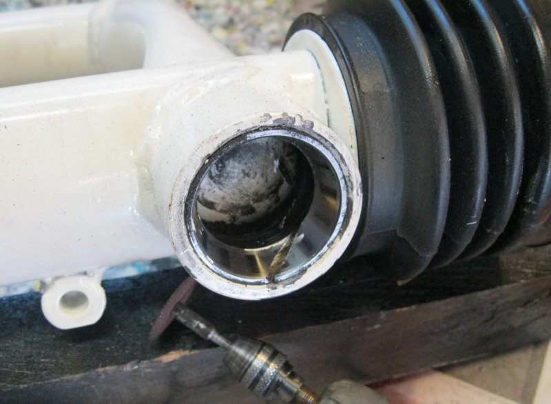
Now it was time for the universal joint. You must slip the rubber boot over the swing arm before attaching the U joint to the transmission’s output flange. The boot must not have any holes in it as the swing arm contains oil to lubricate the universal joint and the splines at the bevel drive. The Joint is held on with 4 hardened 8mm bolts that have a special 12-point 10 mm head. The bolts are deep in the universal joint and I had to use a 10mm box end wrench that I ground to have a very thin wall so that it would fit over the heads of these bolts. You can only get about 1/12 of a turn with each bite of the wrench. I put a drop of Locktight on the threads and tightened each as tight as I could. Once tightened, I slipped the boot over the joint and tightened the two clamps to hold it in place to keep any oil from leaking out. There are 3 oil chambers in the drive train: the transmission, the swing arm and the rear drive. I put the correct amount in each. After several hundred miles I checked all three to make sure oil had not shifted from one chamber to another as will occur if any of the oil seals is not sealing properly. All was as it should be.
The assembly was finished by installing cables (all new), wiring, fuel tank, brake linkage, etc. I also put turn signals on the bike. A factory option was Hella bar-end turn lamps. Emgo makes nice reproduction lights for ¼ the cost of the Hella lamps so I bought those. They look and work fine but the quality is not as good as the Hella. The bulbs look like a big fuses with contacts at both ends. The bulbs go through a large hole at the end of the lamp and an aluminum cap is screwed in to hold the bulb in place, keep out the rain, and serve as an electrical ground. One of the caps did not have sufficient clearance and when tightened down the sping in the socket would bind and break the bulb. I had to shave off a couple mm of material from the cap on my lathe before it would screw down tightly and not crush the bulb.
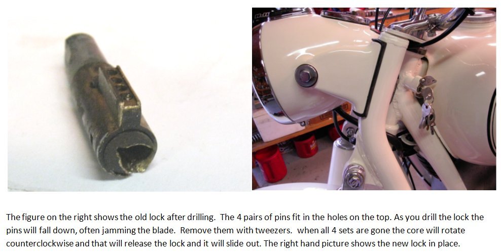
Another issue was the fork lock. The BMW ignition switch uses a “Nail” type key which was popular in Europe at the time. A metal post on the key is pushed into a hole which then closes a spring contact to power the system. Unfortunately, anybody’s BMW key or even a kitchen match will work just as well. Security was provided by a fork lock which used a conventional key. As is often the case with restorations, the fork lock key was missing. Furthermore, there is no identifying number on the lock so a replacement key could not be made. The solution is to replace the lock with a new one which can be obtained from Vech for about $30. Vech has instructions on his web site on how to get the old lock out (which Vech admits seldom works). This is how his assistant told me to get the old lock out: First remove the lock’s cover by prying out its rivet. Do that by driving the blade of a screw driver under it and pry it straight out. The rivet is a single-use item so be sure to order a new rivet with the lock. The cover not only protects the lock but also keeps it from falling out. The lock uses 4 pairs of hardened steel pins to keep the core from rotating when the key is removed. The above-left picture clearly shows the 4 holes where the pins live. Use a ¼” drill bit and drill down the middle of the key slot (see picture above). The lock is brass and will drill easily. When you hit a pin the bit may bind. If so pull the pin out and keep drilling until you can remove all 4 sets of pins. At this point you should be able to turn the core counter clockwise with a screwdriver (I had to use a small punch). It may require a little WD-40 if it hasn’t turned for a while. When turned about 45 deg the entire lock should pull out. It will help if you examine your new lock so you can see how it works before you start. When you put the new lock in smear some grease around it and then make sure it slides freely in its track before riveting the cover back on with a hammer.
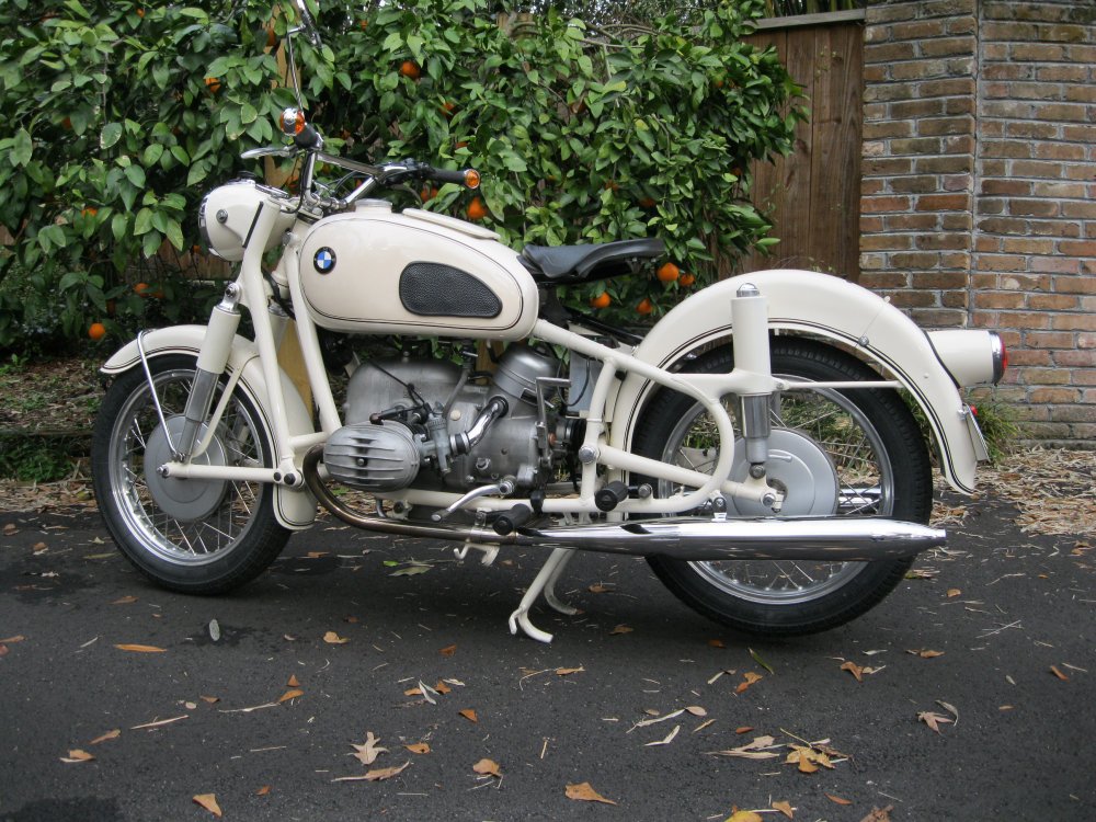
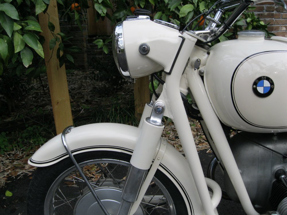
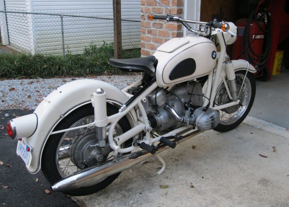
Here are some pictures of the finished bike (yes oranges grow in Mobile).
Return to the Restoration Page