Replace That Bad Diode
A common problem in any restoration is fixing and replacing
inoperative or missing electrical components. If the exact part
cannot be located then the restorer is forced to improvise. Most
amateur mechanics do not have too much trouble figuring out
switches and lamps but usually are stopped cold when they
encounter a diode rectifier lurking under the seat. In this
article I will tell you what a rectifier is and how a simple
replacement from Radio Shack can be used to not only replace a
bad unit but to actually improve it.
From the mid-fifties on, most of the british bikes abandoned
the old generator in favor of an alternator. In the typical
alternator arrangement a permanent magnet on the end of the
crankshaft rotates inside a fixed set of stator coils. The
movement of the magnets causes an alternating voltage to be
induced in the stator coils. While the alternating current
supplies a lot of energy, it can not charge a battery which needs
direct current. A generator with its complicated set of brushes
and commutator puts out direct current but the brushes wear and
have to constantly be replaced. This complexity of course equates
with unreliability. The alternator with only one moving part, the
magnet, is the epitome of simplicity and hence relibility.
 The alternator became practical in the fifties with
the advent of the solid-state rectifier, often called a diode.
Think of a diode as a one-way valve for electricity. Electrons
will pass one way (the direction indicted by the arrows in the
figure) but not the other. The two leads from the stator coils go
to a bridge rectifier which actually contains 4 diodes. During
one phase of the cycle the diodes pass current from the
positively charged stator lead to the positive pole of the
bridge. When the current reverses the diodes direct the current
from the other lead to the bridge's positive pole. Thus, the
alternating current is rectified to a direct current by the
diodes. Most Japanese systems used two sets of stator coils. With
the lights off one set of coils whose output closely matched the
ignition current were connected to the diode. Turning on the
light connected a second set of stator coils which would supply
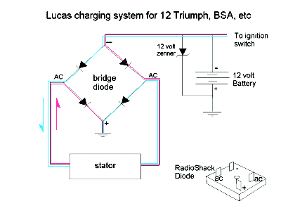
additional current for the headlights. In the Lucas system shown
in the figure, the stator put out enough current to run the
lights all the time and soaked up the additional current with a
zenner diode when the lights were off. Note that the Lucas system
used a positive ground.
The alternator became practical in the fifties with
the advent of the solid-state rectifier, often called a diode.
Think of a diode as a one-way valve for electricity. Electrons
will pass one way (the direction indicted by the arrows in the
figure) but not the other. The two leads from the stator coils go
to a bridge rectifier which actually contains 4 diodes. During
one phase of the cycle the diodes pass current from the
positively charged stator lead to the positive pole of the
bridge. When the current reverses the diodes direct the current
from the other lead to the bridge's positive pole. Thus, the
alternating current is rectified to a direct current by the
diodes. Most Japanese systems used two sets of stator coils. With
the lights off one set of coils whose output closely matched the
ignition current were connected to the diode. Turning on the
light connected a second set of stator coils which would supply
additional current for the headlights. In the Lucas system shown
in the figure, the stator put out enough current to run the
lights all the time and soaked up the additional current with a
zenner diode when the lights were off. Note that the Lucas system
used a positive ground.
Assuming that the wires are intact, failure to charge the
battery will invariably be either a bad stator coil or a blown
diode. The stator coil can be tested by connecting the two stator
wires to an old automotive head light bulb and starting the
engine. Only run the engine at idle speed so you do not blow out
the bulb. If the bulb lights then the stator is OK and the
problem is probably in the diode. Old diodes also suffer from
high back current. On many bikes the positive pole of the bridge
rectifier is connected directly to the battery all of the time. A
leaky diode will insidiously draw current from the battery and
after a week or so without riding the leaky diode will discharge
the battery.
Lets assume that you have determined that your patient needs a
new rectifier. You will probably be shocked at the price as NOS
venders typically charge between $20 and $40 for one and that is
assuming you can even find one. Not to worry! Diodes are rated in
only two critical parameters the maximum current and the peak
backwards voltage. A typical motorcycle alternator puts out about
8-10 amps. Radio Shack offers a full wave bridge rectifier* (part
number 276-1185) that is rated at 25 amps and it will withstand
up to 50 volts, much more than any bike will put out. The price?
A paltry $2.60 at the time of this writing. Furthermore, the RS
diode is state of the art and will be far more efficient and
reliable the original item. The RS diode has 4 spade lugs on it
so it will plug right into your triumph or BSA. On a Honda Dream
I simply replaced the screw lugs on the wires with female spade
ends.
The diode that was on the bike probably had only 3 connections
but the RS diode has 4. Where does the extra wire go? The bike's
original unit had a 4th connection but you didn't notice it
because it was on the mounting lug, the ground. As you look at
the diode, 2 of the wires are marked AC. Connect one of the 2
stator wires to each of the AC posts. That will leave a
"plus" and a "minus" lug. If the bike is a
positive ground like a triumph, connect the "minus" lug
to the battery wire (it originally went to the center lug of the
Lucas diode). Make a jumper lead and connect the "plus"
lug to the motorcycle frame for a ground. If the bike is negative
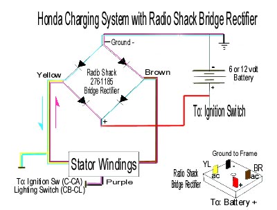
ground like a Honda Dream, Hawk, CB 160 or 90), then reverse the
process. Put the positive battery wire on the "plus"
lug and ground the "minus" lead. William Silver sent me
the diagram below that covers most older Hondas and other
Japanese bikes will be similar.
 The diode gets warm when it is operating
so it needs to be mounted to something that will dissipate the
heat. If you just wrap the thing with tape and stuff it under the
seat you may generate some smoke. The RS diode has a hole through
it and usually it can be mounted right where the original diode
was. The unit is electrically isolated so don't worry about the
metal backing touching the frame. Unfortunately, the mounting
hole is only about 3/16" so a 1/4" or a 6 mm screw will
not go through it. Use a smaller screw and do not try to drill
the hole in the diode bigger.
The diode gets warm when it is operating
so it needs to be mounted to something that will dissipate the
heat. If you just wrap the thing with tape and stuff it under the
seat you may generate some smoke. The RS diode has a hole through
it and usually it can be mounted right where the original diode
was. The unit is electrically isolated so don't worry about the
metal backing touching the frame. Unfortunately, the mounting
hole is only about 3/16" so a 1/4" or a 6 mm screw will
not go through it. Use a smaller screw and do not try to drill
the hole in the diode bigger.
* Radio Shack has recently reduced the number of components
that it sells in many of its stores. If you have trouble finding
it you can order it on line from www.radioshack.com/ click
on components/semiconductors/diodes.